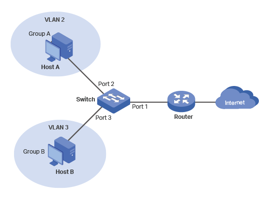
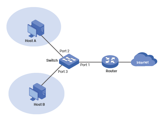
Host A and Host B can NOT communicate with each other
Diagram in TP-Link's Example 1 [1].
Configuration Scheme:
Create VLAN 2 and add ports 1 & 2 to VLAN 2.
Create VLAN 3 and add ports 1 & 3 to VLAN 3.
Keep ports 1, 2 & 3 in VLAN 1 (By default all ports are in VLAN1).
VAN
Egress Rule
PVID
Port 1
VLANs 1,2,3
Untagged
1
Port 2
VLANs 1,2
untagged
2
Port 3
VLANs 1,3
Untagged
3
VLAN Configurations on the Switch
Errors
VLAN 2 is not Host A (nor Port 2) as depicted in the diagram. VLAN 2 is the set of ports,
{1,2}.
Ditto for VLAN 3. It is the set of Ports, {1,3}.
Lack of Clarity
There are no groups in this example, just Host A and Host B.
When VLAN numbers overlap port numbers, there can be confusion.
Since switches can have two-digit port numbers, many people
give VLAN numbers three digits. Unfortunately, many vendors
have a default VLAN 1 that includes all ports, and
you cannot delete it.
The router in this example is a consumer-grade router. VLANs switches are primarily
used in the enterprise. In an enterprise environment, both the switches and router
can have VLANs. The connection between them carries traffic from several VLANs
(a trunk). There are many examples on the Internet that assume both the switches
and routers are VLAN capable. Therefore, it is important to distinguish whether
the router is consumer-grade or enterprise-grade.
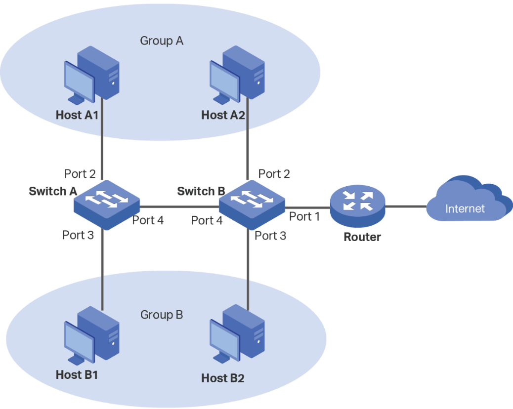
Host A and Host B can NOT communicate with each other
Diagram for Refined Example 1.
Port #
1
2
3
4
5
VLAN 1
U
U
U
U
U
VLAN 200
U
U
VLAN 300
U
U
PVID
1
200
300
1
1
Switch Table for Refined Example 1.
In the above table, the rows show which ports are in each VLAN and whether the port is
tagged (T) or untagged (U).
The last row, Port VLAN ID (PVID), is read by columns e.g. Port 1's PVID is 1 (VLAN 1),
Port 2's PVID is 200 (VLAN 200), etc. Every Port has one and only one PVID. It defines
and limits which other ports it can communicate with. For example, Port 2 can only
communicate with ports that are members of VLAN 200 (Ports 1 & 2).
Introduction to Groups
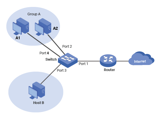
This is an expansion of Example 1. It adds Host A2 to form Group A.
Criteria:
All hosts can connect to Internet.
Hosts in Group A can NOT communicate with Host B.
Diagram for A Simple VLAN Group.
Port #
1
2
3
4
5
VLAN 1
U
U
U
U
U
VLAN 200
U
U
U
VLAN 300
U
U
PVID
1
200
300
200
1
Switch Table for a Simple VLAN Group
Observations
The number of VLANs did not increase. Port 4 was simply added to VLAN 200.
Port 4's PVID is 200 (VLAN 2).
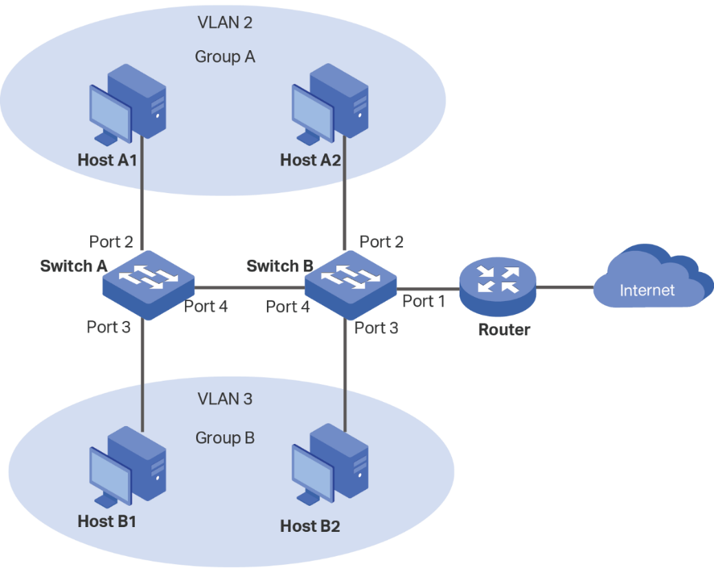
TP-Link's Example 2 in Reference [1]
Criteria:
All hosts can communicate with the Internet.
Hosts in Group A can communicate with other hosts in Group A but NOT those in Group B.
Hosts in Group B can communicate with other hosts in Group B but NOT those in Group A.
Diagram in TP-Link's Example 2 [1].
VLAN 1
VLAN 2
VLAN 3
Switch A
Ports 2-4
Ports 2,4
Ports 3,4
Switch B
Ports 1-4
1,2,4
Port 1,3,4
VLAN Configuration on Switch A and Switch B
Switch
Switch A
Switch B
Port
2
3
4
1
2
3
4
Egress Rule
Untagged
Untagged
Tagged
Untagged
Untagged
Untagged
Tagged
PVID
2
3
1
1
2
3
1
Egress Rules and PVID Settings on Switch A and Switch B.
Errors
VLAN 2 is not Host A1 and Host A2. It is a set of Ports.
Ditto for VLAN 3.
Lack of Clarity
Again, when VLAN numbers overlap port numbers, there can be confusion.
In TP-Link's diagram, the trunk is not labeled.
VLAN Tags and their purpose is not even mentioned. This is supposed to be
a tutorial.
The tables are difficult to read for multiple reasons:
The headings are not emphasized. It is not obvious that
in the second table, all of the second row is a heading.
In the first table, you must pay attention to dashes and commas
to determine which Ports are members of which VLANs.
In TP-Link's Example 1, Egress Rules and PVID are column headings.
In TP-Link's Example 2, Egress Rules and PVID are row heading.
You should be consistent in a tutorial.
You have the look in two tables to determine if a port is a member of VLAN.
and whether the port is tagged or untagged.
The two switches are going to be set up one at a time. Yet, the parameters
for the two switches are merged into one table. Clearly, the data
should be organized so there is one table for Switch A and another
table for Switch B.
They prioritized conciseness over clarity.
Refined (TP-Link) Example 2
Criteria:
All hosts can communicate with the Internet.
Hosts in Group A can communicate with other hosts in Group A but NOT those in Group B.
Hosts in Group B can communicate with other hosts in Group B but NOT those in Group A.
Diagram for Refined Example 2.
Port #
1
2
3
4
5
VLAN 1
U
U
U
T
U
VLAN 200
U
T
VLAN 300
U
T
PVID
1
200
300
1
1
Switch A - Table for Refined Example 2.
Port #
1
2
3
4
5
VLAN 1
U
U
U
T
U
VLAN 200
U
U
T
VLAN 300
U
U
T
PVID
1
200
300
1
1
Switch B - Table for Refined Example 2.
Trunks and VLAN Tags
Trunks are used to eliminate multiple cables. On one end, packets, from multiple
sources, are merged, and on the other end, the packets are separated according to the
source that generated them. To accomplish this, on the transmitting side, a VLAN Tag
that specifies the source is added to the packet. On the receiving end, the VLAN Tag is
removed from the packet.
This requires that for each packet traveling across the trunk, there must be
a VLAN on the other side with the same ID to receive the packet. However, the two VLANs
can have different members. For example, at Switch A, VLAN 200 members are Ports 2 and 4,
and on Switch B VLAN 200 members are Ports 1,2 and 4. Thus, in Switch A, Ports 2 and 4
can only communicate with each other, but in Switch B Ports 1,2 and 4 can communicate with
each other.
The Native VLAN
Now that we know about Trunks and VLAN Tags, there is one exception.
Since all the other VLANs have VLAN Tags, one of the VLANs does
not have to have a VLAN tag. This is referred to as the "Native" VLAN.
On Cisco fully monitored switches, you can specify which VLAN is the
Native VLAN. On switches with less features, you cannot specify
which VLAN is the Native VLAN. Some switches such as Netgear's Series -
Easy Smart Managed Essentials, may not have "Native" VLAN.
The Management VLAN
There is a reason that most VLAN switches designate VLAN 1 as the default VLAN and it
contains all ports and all of them are untagged. This setup makes VLAN 1 ideal for a
dedicated magagemenet VLAN. If all the switches are on the same subnet, then from one location,
you can configure any switch.
Since Switch A has two spare ports, I decided to use Port 1 for management. The modify
Switch A and Switch B tables are below.
Port #
1
2
3
4
5
VLAN 1
U
U
U
U
U
VLAN 100
U
U
T
VLAN 200
U
T
VLAN 300
U
T
PVID
1
200
300
1
1
Modified Switch A Table -
VLAN 1 is for Management.
Port #
1
2
3
4
5
VLAN 1
U
U
U
U
U
VLAN 100
U
U
U
T
VLAN 200
U
U
T
VLAN 300
U
U
T
PVID
100
200
300
1
1
Modified Switch B Table -
VLAN 1 is for Management.
We now have four VLANs with VLAN 1 dedicated to managing the switches. It
cannot be used to telnet or ssh into the hosts. It only serves one
purpose, to manage the switches. However, it can ping both switches,
and if the ping request goes across the trunk, it nor the ping reply
are tagged. Hence, VLAN 1 is not
only the default VLAN, it is the "Native" VLAN.
Observe that in the tables that Port 4 is untagged in VLAN 1 and tagged in the other VLANs.
Trunk ports can be untagged in one VLAN and tagged in another VLAN [4]. All access ports
are untagged.
We are loosely using the term tagged and untagged VLANs. The only thing that is actually
tagged is the traffic that go across the trunk.
CAM or MAC Tables
CAM or MAC tables on a VLAN Switch are per VLAN. For example,
on Switch B, VLAN 2's MAC table only has entries for (1) port 2
and its MAC address and (2) Port 4 and its MAC address. It does
not have an entry for the router because it is in a different
VLAN.
References
For good illustrative explanations of Trunks, VLAN Tags, and
the Native VLAN, see the references [1] and [2]. However,
the first reference assumes the router is Enterprise-grade
with VLAN capability. Consumer-grade router do not have VLAN
capability.
For diagnostic purposes, most VLAN switches include a port mirroring feature that
allows you to mirror and monitor one or more ports. This feature does require
an unused port and software such as Wireshark.
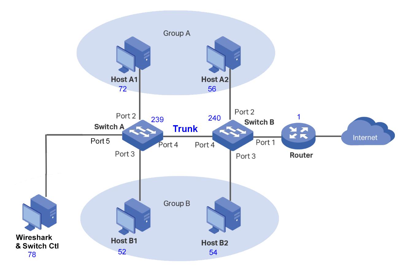
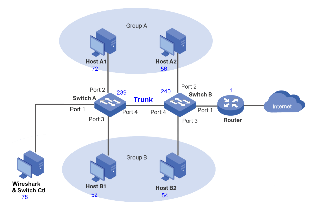
For this example, I selected Port 5 on Switch A as the mirror destination port. See
the diagram below. To help me keep track of which device was which, in my implementation,
the numbers in blue beside the devices are the last octet of the IP address.
Diagram for Monitoring Ports in Refined Example 2.
It is important that the mirror destination port only receives traffic from the mirror source.
Hence, the port can only be in one VLAN,
and there must not be any other port(s) in this VLAN (Isolated).
This usually requires:
Creating a separate VLAN for the destination port.
Setting the PVID for this port to the new VLAN.
Removing the destination port from VLAN 1, which
is the default VLAN. Usually, you cannot delete VLAN 1,
but you are allowed to modify it.
This does not change the fundamental behavior of the switch. You are only making changes to
a vacant port that was not used.
The changes in the Switch Tables are highlighted in light green below.
They are all in Switch A, Column 5.
Port #
1
2
3
4
5
VLAN 1
U
U
U
U
VLAN 100
U
T
VLAN 200
U
T
VLAN 300
U
T
VLAN 500
U
PVID
1
200
300
1
500
Switch A Table - With Monitoring Port.
Port #
1
2
3
4
5
VLAN 1
U
U
U
U
U
VLAN 100
U
U
U
T
VLAN 200
U
U
T
VLAN 300
U
U
T
PVID
100
200
300
1
1
Switch B - Table for Refined Example 2.
I wanted to view VLAN Tags, so I selected the mirror source port to be the trunk port (Port 4).
The host-to-host and host-to-router ping traces are given in the tables below.
Source
Destination
Ping Request VLAN Tag
Ping Response VLAN Tag
Host A1
Host A2
200
200
Host A2
Host A1
200
200
Host B1
Host B2
300
300
Host B2
Host B1
300
300
Wireshark Trunk Host-to-Host Traces
Source
Destination
Ping Request VLAN Tag
Ping Response VLAN Tag
Host A1
Router
200
100
Host B1
Router
300
100
Host A2
Router
200
100
Host B2
Router
300
100
Wireshark Trunk Host-to-Router Traces.
Later, I decided that I wanted to analyze everything about this network. So, I added a
second monitoring port to Switch B, Port 5.
Port #
1
2
3
4
5
VLAN 1
U
U
U
U
VLAN 100
U
U
U
T
VLAN 200
U
T
VLAN 300
U
T
VLAN 500
U
PVID
1
200
300
1
500
Switch A Table - With Monitoring Port.
Port #
1
2
3
4
5
VLAN 1
U
U
U
U
VLAN 100
U
U
U
T
VLAN 200
U
U
T
VLAN 300
U
U
T
VLAN 555
U
U
PVID
100
200
300
1
555
Switch B Table - With Monitoring Port.
Netgear GS105Ev4 and GS308E Switches
I implemented this network twice - once with Netgear GS105Ev2 (5-ports) switches
and once with Netgear GS308E (8-ports) switches.
I am still investigating how these switches operate, but they do not seem that smart to me.
In the example above, every time the routers send a ping response, it goes
to every host. When Host A2 pings the router, it goes across the trunk to Host A1.
A word search of both User Manuals did not find the word "Native".
Native VLANs
Not all switches have a "Native" VLAN e.g. the Netgear Series: East Smart Managed Essentials".
If there is no "Native" VLAN, then all traffic on all trunk ports should have a VLAN Tag. If
you are mirroring a trunk port, and you do not see a VLAN tag, then your designation
port is not isolated from the other VLANs.
No Spare Ports
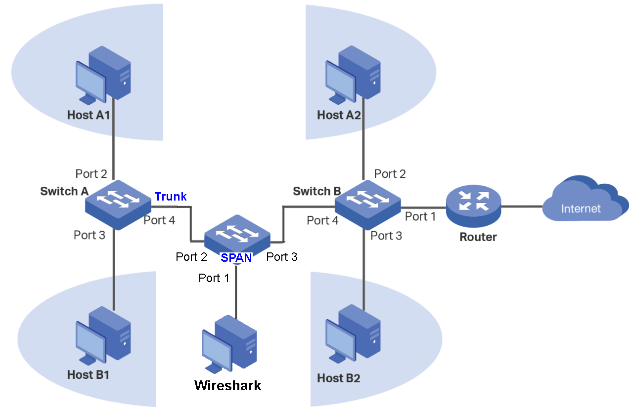
If you do not have a spare port, use a network TAP (Test Access Port) or configure another switch as a SPAN
(Switch Port Analyzer for Networks).
The SPAN Switch must have mirroring capabilities, but you set it up without any VLANs.
You then connect the port you want to monitor (source) into and out of any two ports
of the SPAN Switch. You can then mirror either the input or output.
The diagram below depicts a SPAN.
Diagram for Monitoring Ports in Refined Example 2.
Because of their smaller size, 5-port switches are often used as SPANs.
Add a 3rd Host to Group A at Switch A
Criteria:
Add a 3rd Host to Switch A - Group A.
All host can communicate with the Internet.
Hosts in Group A can communicate with other hosts in Group A but NOT those in Group B.
Hosts in Group B can communicate with other hosts in Group B but NOT those in Group A.
See the diagram and tables below.
Diagram for Adding a 3rd Host to Group A at Switch A.
Adding a Network 3rd Group A Host at Switch A, only requires two changes to the Switch A Table.
Changes to the tables are highlighted in light green.
Port #
1
2
3
4
5
VLAN 1
U
U
U
T
U
VLAN 200
U
T
U
VLAN 300
U
T
U
PVID
1
200
300
1
1
Switch A - Adding an A3 Host to Switch A.
Port #
1
2
3
4
5
VLAN 1
U
U
U
T
U
VLAN 200
U
U
T
VLAN 300
U
U
T
PVID
1
200
300
1
1
Switch B - Adding an A3 Host to Switch A.
After troubleshooting, you can remove the Wireshark Host at Port 1 on Switch A.
Adding a Shared Network Printer
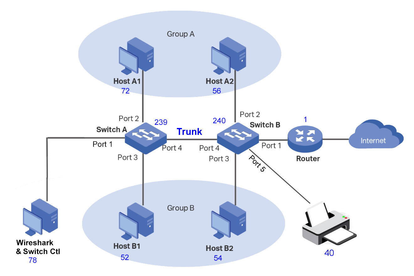
A shared Network Printer is added to the previous example.
Criteria:
All hosts can communicate with the Internet.
Hosts in Group A can communicate with other hosts in Group A but NOT those in Group B.
Hosts in Group B can communicate with other hosts in Group B but NOT those in Group A.
All hosts can communicate with the Printer.
See the diagram and tables below.
Diagram for Adding a Network Printer.
Adding a Network Printer to Switch B, Port 5, requires making two changes to the Switch B Table:
Port #
1
2
3
4
5
VLAN 1
U
U
U
T
U
VLAN 200
U
U
T
VLAN 300
U
U
T
PVID
1
200
300
1
1
Switch A - Adding a Network Printer.
Port #
1
2
3
4
5
VLAN 1
U
U
U
T
U
VLAN 200
U
U
T
U
VLAN 300
U
U
T
U
PVID
1
200
300
1
1
Switch B - Adding a Network Printer.
After troubleshooting, you can remove the Wireshark Host at Port 1 on Switch A.
Forcing a Router VLAN Tag
This is the same as TP-Link's Example 2, but we are going to force the router to use a VLAN
Tag.
Criteria:
All hosts can communicate with the Internet.
Hosts in Group A can communicate with other hosts in Group A but NOT those in Group B.
Hosts in Group B can communicate with other hosts in Group B but NOT those in Group A.
Force the Router to use a VLAN Tag when traversing the trunk.
The diagram is the Same as for Monitoring Ports.
You will need to create a new VLAN for this.
On Switch B, add a new VLAN for the Router (Port 1), and make the new VLAN the PVID
for Port 1.
Since Port 1 must communicate with Ports 2,3 and 4, all of them must be members of
the new VLAN. I chose an ID of 88 for the new VLAN. For the Netgear GS105Ev2 Switch
that I used, it did not complain when I made made VLAN 88 the same as VLAN 1
(and it also worked).
To recieve a response at Switch A, there must be a corresponding VLAN 88.
The trunk must be in this VLAN and Ports 2 and 3.
Now, whenever you ping the router, if the response going across the trunk it
a VLAN 88 Tag.
Port #
1
2
3
4
5
VLAN 1
U
U
U
T
U
VLAN 200
U
T
VLAN 300
U
T
VLAN 88
U
U
T
PVID
1
200
300
1
1
Switch A - Forced Router VLAN Tag.
Port #
1
2
3
4
5
VLAN 1
U
U
U
T
U
VLAN 200
U
U
T
VLAN 300
U
U
T
VLAN 88
U
U
U
T
PVID
88
200
300
1
1
Switch B - Forced Router VLAN Tag.
Source
Destination
Request2
Response
xxx.xxx.xxx.78
xxx.xxx.xxx.56
200
200
xxx.xxx.xxx.56
xxx.xxx.xxx.78
200
200
xxx.xxx.xxx.52
xxx.xxx.xxx.54
300
300
xxx.xxx.xxx.54
xxx.xxx.xxx.52
300
300
xxx.xxx.xxx.72
xxx.xxx.xxx.1
200
88
xxx.xxx.xxx.56
xxx.xxx.xxx.1
200
xxx.xxx.xxx.52
xxx.xxx.xxx.1
300
xxx.xxx.xxx.54
xxx.xxx.xxx.1
300
Ping Requests and Ping Responces.
Realistic Test Network
Segregate the following traffic: Linux, Microsoft, Phone, IoT, and Social Media.